Description
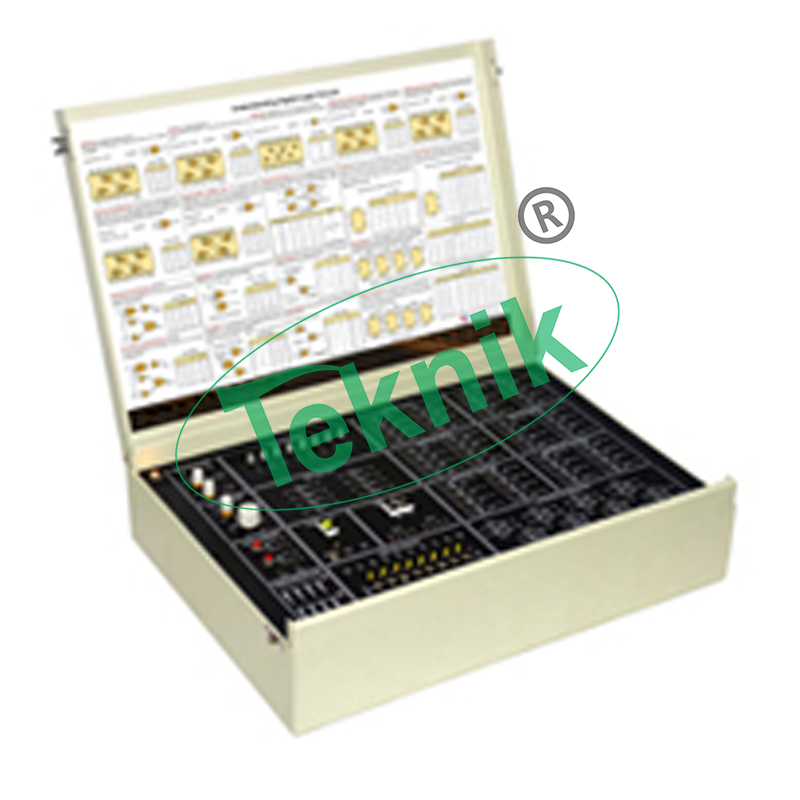
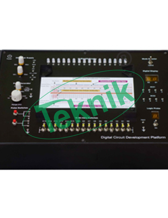
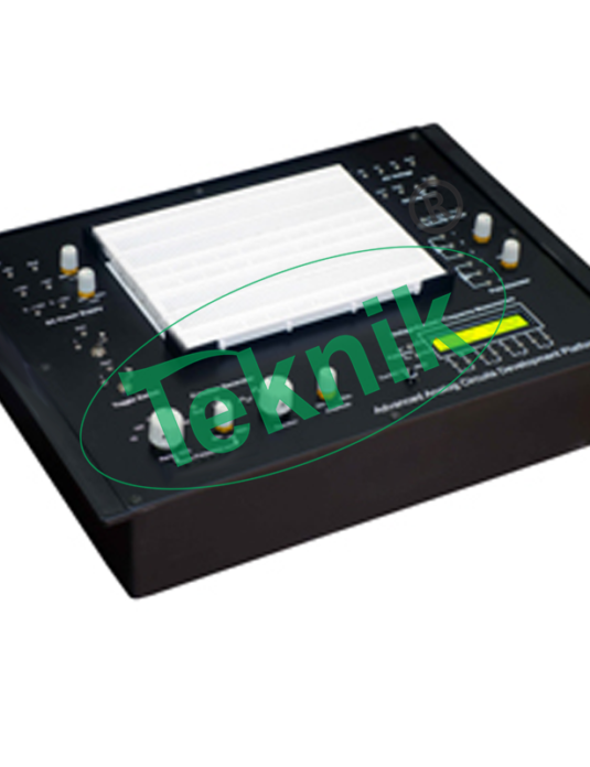
DIGITAL LOGIC CIRCUITS EXPERIMENT PLATFORM COMPRISES OF FOLLOWING BLOCKS:-
- DC Power Supplies
- pulse Switches
- Pulse Generator
- Sockets (20 pins)
- 8 bit Data Switches
- 8 bit bicolor LED display
- Logic Probe
- Digital display
SCOPE OF LEARNING:-
- Logic AND gate and verify its Truth table
- Logic OR gate and verify its Truth table
- Logic NOT gate and verify its Truth table
- Logic NAND gate and verify its Truth table
- Logic NOR gate and verify its Truth table
- Logic algebra
- Application of logic gate circuit
- Implementation of simple logic design
- Digital combinational logic circuits
- Application of D Flip-flops as Shift Register
- Application of JK Flip-flops as Up-Down Counter
TECHNICAL SPECIFICATIONS:-
- DC Power Supplies : + 5V, 1A +3V to +15V, 500 mA (variable)- 3V to -15V, 500 mA (variable)
- Pulse Generator : 1Hz to 1MHz in 6 steps (Variable in between the steps)
- Amplitude : 5V (TTL)
- Duty Cycle: 50 %, TTL output
- Pulse Switches : 2 no’s (Push to ‘On’)
- Data Switches : 8 no’s (Toggle switches) (TTL output)
- LED Display (Bicolor) : 8 no’s (TTL input)
- BCD to Seven Segment Display : 2 no’s
- Logic Probe : Logic level indicator for TTL input ‘H’ = HIGH and ‘L’ = LOW
- ZIF Sockets : 2 no’s (20 pins)
- Breadboard (solder less) : 175 mm x 61 mm (840 tie points)
- Operating Conditions : 0-40 C, 80% RH
- Mains Supply: 110-220V ±10%, 50/60Hz
** Note:-The content of the product and specification are subject to change without prior notice for continuous improvement. Images shown are for representation purpose only. “MICROTEKNIK” keeps the right to modify the content in the product without prior notice.


